| Products |
| Company |
| Distributors Training & Support Contact Customers About EOIS |
| Applications |
| Automotive Design Aerospace Animation Mold,Die Inspection Medical Satellite |
| Technology |
| Image Gallery VRML Gallery MoiréInterferometry Links |
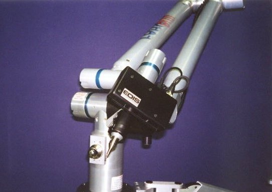
Mini-Moiré Digitizer for Portable Arms
Features
- Portable
- Simple and intuitive operation, just point and shoot
- 6 or 7 axis rotation for scanning around complex parts
- High-speed, high-density digitizing
- Optical non-contact for delicate or non-rigid parts
- Flexible scanning with touch probe, laser line and Moiré options
The Mini-Moiré digitizer for Portable Arms is designed to attach to portable arm CMMs such as the FaroArm® shown above. It provides high-speed, high density data acquisition in a portable system.
The Mini-Moiré sensor uses white light illumination, for non-contact measurement. This light is completely eye-safe, but it does not work for very dark or shiny surfaces. For this reason, we have included a laser line source in the latest sensor. The laser source works over a larger range of surfaces, and also gives more detailed data on small features. This gives our Mini-Moiré sensor all the capabilities of the competing laser line products, as well as the high-speed and high-density capability of Moiré technology.
Hardware Specifications
| MODEL | MMM.3 | MMM.4 | MMM.6 |
| XY range - FOV (mm) | 75 | 100 | 150 |
| Z range - DOF (mm) | 40 | 60 | 80 |
| XY resolution - pixel spacing (mm) (1) | 0.15 | 0.2 | 0.3 |
| Z resolution - accuracy (mm) (2) | 0.08 | 0.1 | 0.15 |
| Standoff distance (mm) | 175 | 250 | 250 |
| Capture speed (pix/sec) (3) | 300K | ||
| Processing speed (pts/sec) (4) | 150K | ||
| Size (mm) | 125 x 175 x 50 | ||
| Weight (Kg) | 0.7 | ||
| Camera resolution (pix) | 640 x 480 | ||
| Portable Arm Interface | RS232 serial | ||
| System accuracy (mm) (5) | 0.2 | 0.3 | 0.4 |
Notes:
- X,Y resolution is determined by the number of pixels in the camera. One XYZ data point is calculated for each pixel of the camera.
- Z resolution is essentially the same as the total XYZ accuracy of the sensor. It is defined as the 3-sigma error between measured and nominal XYZ coordinates, over the full range of the sensor. It is calculated by measuring marked precision plates at several positions over the range of the sensor.
- Capture speed indicates maximum sustained capture speed for multiple images.
- Processing performed in parallel with capture, so capture can continue at maximum speed. Processing speed given for typical EOIS supplied computer (PII/400Mhz).
- System accuracy defined as 3-sigma error between measured and known XYZ coordinates of 100mm diameter master cylinder.
Software Functions
- Sensor alignment
- Single point digitizing with touch probe
- Sweeping line digitizing with laser line projector
- Area digitizing with Moiré projector
- Image Editing
- XYZ point reduction (space sampling)
- XYZ cross section calculation
- Output formats:
- IGS point clouds and cross-section lines
- STL polyface models
- ASCII text point clouds
- BMP greyscale images